Intro
This article is a part of the Edgeboard RISC-V series. Check out other articles as well if you came in through a search engine.
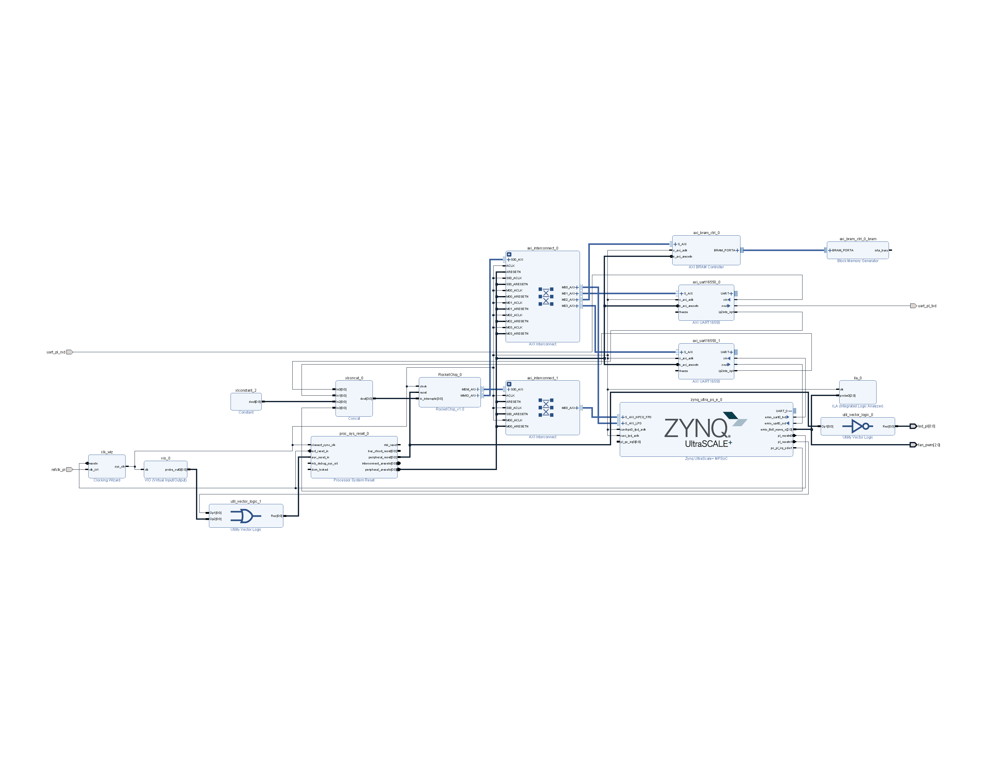
Besides setting up RISC-V bootloader, we need to have the PS side of Zynq set up properly for a proper system as well as ease of debugging. The BSP from ALINX will no longer be used - a new system will be used. The PS has the following roles in the system:
- Provide DDR and MMC to RISC-V
- Provide reset signals
- Provide Internet access
- Control PWM fan on the board
Note that the system block design has changed since the previous introducing article. The updated diagram and updated PDF can be found below.
Note that this article is not a detailed walkthrough of the entire process, and may subject to missing or inaccurate steps. You should only take this article as an overall guidance.
PS bootloader & kernel setup
The PS kernel will be built from the linux-xlnx tree to get support for all devices in the Zynq MPSoC chip. We will be using the PetaLinux SDK for generating the kernel, device tree, as well as FSBL, U-Boot and PMU firmwares. The PetaLinux SDK is also capable of creating a rootfs via the Yocto Project, but we will only be using that feature very lightly.
Create the PetaLinux project and import hardware description exported from Vivado:
$ petalinux-create --type project --template zynqMP --name rocket-zynqmp
$ cd rocket-zynqmp
$ petalinux-config --get-hw-description=..
Review the configuration, set hardware properties correctly, and save the configuration.
Device tree generation
My early attempts of modifying the decompiled device tree from ALINX BSP did not turn out very well: the compiled kernel often wouldn't boot with mysterious failures. The proper way to generate device tree for a ZynqMP platform is to utilize the device tree include mechanism: PetaLinux generates a basic configuration from exported hardware definition (hwdef file, which may contain a bitstream). A system-user.dtsi definition is then provided to make changes to the generated device tree.
/include/ "system-conf.dtsi"
/ {
    chosen {
        bootargs = "earlycon console=ttyPS0,115200 clk_ignore_unused cpuidle.off=1";
    };

    reserved-memory {
        #address-cells = <2>;
        #size-cells = <2>;
        ranges;
        riscv@40000000 {  /* RISC-V */
            reg = <0x0 0x40000000 0x0 0x3ff00000>;
        };
    };
};

&sdhci1 {
    disable-wp;
    no-1-8-v;
};

&ttc0 {
    #pwm-cells = <1>;
    status = "okay";
    xlnx,ttc-clk0-freq-hz = <100000000>; /* PS_LSBUS_CLK */
    xlnx,ttc-clk1-freq-hz = <100000000>;
    xlnx,ttc-clk2-freq-hz = <100000000>;
    xlnx,ttc-clk0-clksrc = <0>;          /* the clock is internal */
    xlnx,ttc-clk1-clksrc = <0>;
    xlnx,ttc-clk2-clksrc = <0>;
};
The most notable and important modification is the reserved-memory node, which prevents PS kernel from using 0x40000000-0x7ff00000, as the range is already allocated to RISC-V. Failing to do so may result in PS kernel crash (silently at most times) due to its data in the zone being destroyed by RISC-V.
The SDHCI1 controller is modified to add quirks to disable voltage switching and write-protect detection.
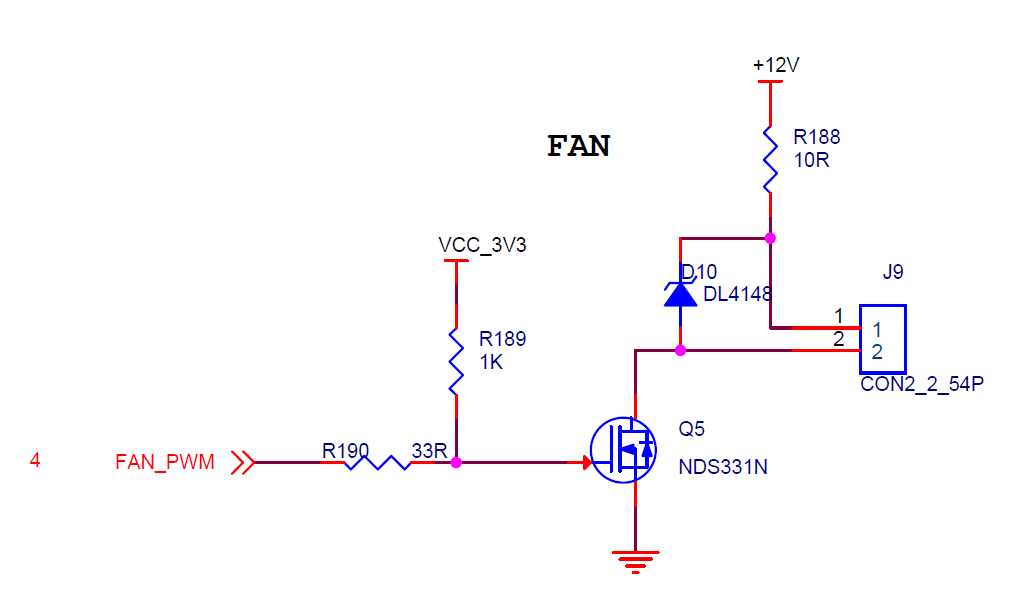
The TTC cell is added for PWM control of the fan attached onboard. A MOS is connected to the B11 pin in PL, and then drives the fan:
U-Boot special configuration
As the previous article on RISC-V software design states, the RISC-V part of the system will use a MMC controller, notably the mmc1 controller for persistent storage. Due to the Linux driver of Zynq's Arasan SDHCI host controller requiring a working IRQ, only one processor (ARM or RISC-V) may use the controller at a time. This is achieved via some U-Boot magic:
env set bootcmd 'fatload mmc 0 ${netstart} image.ub && fdt addr ${fdtaddr} && fdt move ${fdtaddr} 0x7000000 && fdt addr 0x7000000 && fdt set /amba/mmc@ff170000 status disabled && env set bootargs earlycon console=ttyPS0,115200 clk_ignore_unused cpuidle.off=1 root=/dev/mmcblk0p2 rw rootwait && bootm ${netstart} - 0x7000000'
The actual boot command is then:
fatload mmc 0 ${netstart} image.ub
fdt addr ${fdtaddr}
fdt set /amba/mmc@ff170000 status disabled
env set bootargs earlycon console=ttyPS0,115200 clk_ignore_unused cpuidle.off=1 root=/dev/mmcblk0p2 rw rootwait
bootm ${netstart} - ${fdtaddr}
What happened is then easily understood: after loading the U-Boot image image.ub, the FDT is edited to have the mmc1 or /amba/mmc@ff170000 node status set to disabled. The PS kernel then will not initialize the device or register IRQ handler for it. If this is not done, RISC-V will most likely fail to get an IRQ when it is expecting one, while the PS is constantly receiving IRQs with no apparent command issued (from its point of view). An altboot command is also stored to run PS with the mmc1 node in status = "okay" if the SD card needs to be accessed from PS.
Make sure to save the environment variables to FAT after setting the variables:
ZynqMP> env save
Kernel options
Two features need to be added to the PS kernel: PPP (CONFIG_PPP) and NFS server (CONFIG_NFSD); they are used for Internet and filesystem access. Also, to avoid conflict with the TTC PWM kernel module, make sure to disable the Cadence TTC timer driver (CONFIG_CADENCE_TTC_TIMER). Configure the PS kernel with:
$ petalinux-config -c kernel
Kernel modules
A custom kernel module for the TTC counter to work as a PWM device is needed for fan control. With this Xilinx AR, we can have the module build along the kernel. We can then acquire the installed module directory (as in /lib/modules) from the generated rootfs image:
$ cd images/linux
$ mkdir rootfs-mount
$ sudo mount -o loop rootfs.ext4 rootfs-mount
$ cd rootfs-mount/lib/modules # tar the modules up and save them for later use
BOOT.BIN
After building the PetaLinux project via petalinux-build, the FSBL, PMU FW, bitstream, and some misc initialization files need to be packaged into a single BOOT.BIN file:
$ petalinux-package --boot --fsbl zynqmp_fsbl.elf --fpga system.bit --u-boot --force
When there's a new bitstream available, but no big changes that would affect FSBL and U-Boot, we can simply regenerate the BIN file by swapping out system.bit in the above command.
Rootfs setup
For ease of accessing the RISC-V filesystem, I decided to put the RISC-V boot and root partition on the SD card (removable), while assigning PS with the eMMC storage. This resulted in a small problem: we need a system up and running to unpack the real rootfs into the eMMC chip. A tiny buildroot initramfs is used to perform this task (I failed to get yocto behave the way I wanted). The following tools are needed in the initramfs to perform this task:
- fdisk
- dosfstools
- e2fsprogs
- tar
- gzip
Note that the busybox version of the tools above may show limited features. For example, you may need to untar a .tar.gz archive as follows:
$ gzip -d < archive.tar.gz | tar xvf -
The real rootfs would be a generic aarch64 Archlinux ARM snapshot. As we have network access (onboard Ethernet) and a rather decent CPU (4-core Cortex-A53), Archlinux ARM would provide extreme flexibility over the fixed rootfs solution. Create a FAT32 partition followed by an EXT4 partition, copy BOOT.BIN and image.ub to the FAT32 partition, and untar the rootfs image into the EXT4 partition. Remember to untar the kernel modules acquired from the previous step as well.
PL reset & clock
The ZynqMP PS IP block provides up to 4 pl_resetnx ports for use to generate reset signals for PL logic besides the Power-On Reset mechanism. This AR clearly states that the reset port from PS IP block is simply a GPIO pin, and can be controlled from PS. A small script would be sufficient to control the pin status:
#!/usr/bin/env bash

set -e

die() {
        echo $1
        exit 1
}

if [ $# -gt 1 ]; then
        die "usage: $0 [pin value]"
fi

pin_number=510
gpio_dir=/sys/class/gpio/gpio${pin_number}
gpio_export=/sys/class/gpio/export

toggle() {
    if [ ! -d "${gpio_dir}" ]; then
           echo ${pin_number} > ${gpio_export} # enable pin 510 - PL Reset 1
    fi
    echo -n Pin direction:\
    cat ${gpio_dir}/direction
    echo -n Old value:\
    cat ${gpio_dir}/value
    echo $1 > ${gpio_dir}/value
    echo -n New value:\
    cat ${gpio_dir}/value
}

if [ $# -eq 0 ]; then
    echo Resetting PL...
    toggle 1
    sleep 1
    toggle 0
else
    echo Setting reset to $1...
    toggle $1
fi
The default polarity of the pin is low-active, but we're actually using it as high-active. This satisfies our use just well: the RISC-V part stays in reset until we pull down the reset pin.
If you look closely into the block design diagram, you will find out that we do not use pl_clockx ports from the PS IP block: this is intended, as Linux's Common Clock Framework may mess with the RISC-V clock. A fixed oscillator output is used instead.
PS TTC for PWM
The Triple Time Counter inside PS can be used as a PWM source with the kernel module. A simple bash script can then be used to control the PWM duty ratio of the fan:
#!/usr/bin/env bash

set -e

die() {
        echo $1
        exit 1
}

if [ $# -ne 1 ]; then
        die "usage: $0 <duty ratio>"
fi

pwm_number=0
pwm_dir=/sys/class/pwm/pwm${pwm_number}
pwm_export=/sys/class/pwm/pwmchip0/export
pwm_period=1000
pwm_duty=$(echo "($1 * ${pwm_period}) / 1" | bc)

if [ ! -d "${pwm_dir}" ]; then
       echo ${pwm_number} > ${pwm_export} # enable pwm #0 - Fan @ B11
fi

echo ${pwm_period} > ${pwm_dir}/period
echo ${pwm_duty} > ${pwm_dir}/duty_cycle
echo 1 > ${pwm_dir}/enable

echo Done.
Note that the PWM duty ratio does not reflect real RPM for a DC fan. For the Edgeboard FZ3, a mere 3% can keep the chip cool at 40 Celcius, compared to just 35 Celcius with 100%. To prevent damage in the case of forgetting to set PWM resulting in the fan not turning (without setup TTC will output constant 0), call the script in rc.local or some other mechanism.