Meet the Baidu Edgeboard ZU3EG - Edgeboard RISC-V Series
Intro
This article is a part of the Edgeboard RISC-V series. Check out other articles as well if you came in through a search engine.
Someone in the TUNA Embedded Telegram group mentioned that there has been a cheap Xilinx ZynqMP UltraScale+ board made by Baidu back in January, 2020. The board plus some necessary accessories (a pre-installed fan, a USB-A to mini USB-B cable, a power supply, a 16 GB SD card) costed 1075 CNY on the Chinese online shopping site Taobao at the time of purchase. With Xilinx ZynqMP XA ZU3EG (Automotive grade) it's quite a bargain. This article is to introduce the basic features and the hardware setup for the RISC-V project.
Board features
The board (Edgeboard FZ3) features a handful of low-speed and high-speed I/O ports, along with quite a few peripherals available for use. Due to its designed usecase of performing FPGA-accelerated AI inference, not too much I/O is connected to the PL part of the Zynq MPSoC. Fortunately we still have some GPIO pins connected to the PL, and that should be sufficient as we only need a serial port from PL for RISC-V. The exact features used will be discussed in the RISC-V Hardware Design: System & Block Design - Edgeboard RISC-V Series article.
Gathering the various I/O and peripheral resources as follows (fabricated peripheral cores in the PS are not listed here):
- ZynqMP system (XAZU3EG-1SFVC784I)
- PS side
- 2GB DDR4 DRAM: Micron MT40A512M16LY-062EIT
- 256Mbit QSPI Flash: Micron MT25QU256ABA1EW9-0SIT
- 8GB eMMC Flash: Micron MTFC8GAKAJCN-4M
- EEPROM: Microchip 24LC04B-I/SN
- Mini DisplayPort with 2 GT lanes
- USB: 1x 3.0, 1x 2.0
- GPHY: Micrel KSZ9031RNXIC, with RJ45 port
- USB UART: Silicon Labs CP2102, with miniUSB-B
- MicroSD slot
- PCIe 2.0 x1, with 1 GT lane
- CAN: TI SN65HVD232, 2 pins in 44-pin header
- JTAG (without PSRST)
- PL side
- RS485: MAX3485, 2 pins in 44-pin header
- GPIO 38x (excluding VCC/GND, CAN, RS485) in 44-pin header
- MIPI 25-pin
- BT1120 32-pin
- LED 1x
- 25MHz reference clock: Silicon Labs Si5332BD11025-GM2
Additional accessories and modifications
The board needs some additional accessories to work as the platform for the RISC-V project:
- The 44-pin GPIO port on the board didn't come with pin headers soldered. A 44-pin (in 2x22) header needs to be purchased and then soldered onto the board.
- Consequently, a solder iron kit is also needed (the iron, solder, rosin flux, etc.)
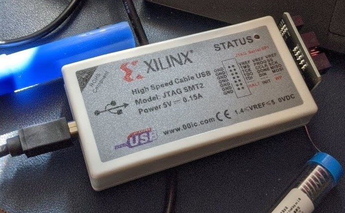
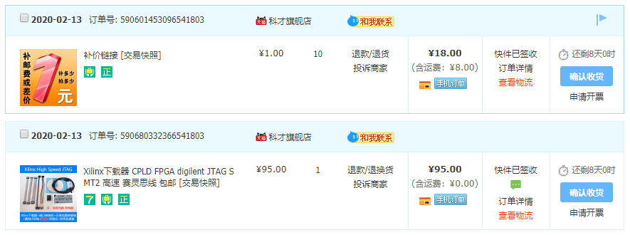
- The JTAG debug port, which is used for programming FPGA bitstreams, does not have a debug cable chip integrated. A Digilent SMT2 JTAG cable needs to be purchased.
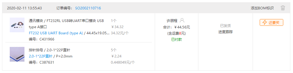
- The board's GPIO headers are of 2.00mm width. Some 2.00mm-to-2.54mm Dupont cable is needed.
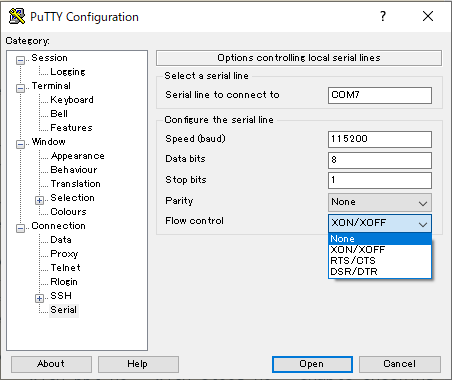
- Finally, the UART signal from RISC-V system requires a USB TTL to be read by PuTTY on the development system.
The order information for the required parts can be found below.

It took about a week to collect all the parts in mail, compared to which would be about three days if it were not for the recent COVID-19 event. After soldering the GPIO headers and connecting the cables, the ZynqMP system is ready for test.
Testing the system
The system was configured to boot from SD card, which comes with a FSBL that holds Baidu's accelerator bitstream, and a root filesystem with self-hosting tools. Tools like GCC, Clang, and CMake are ready in the image, kudos for the engineers at Baidu.
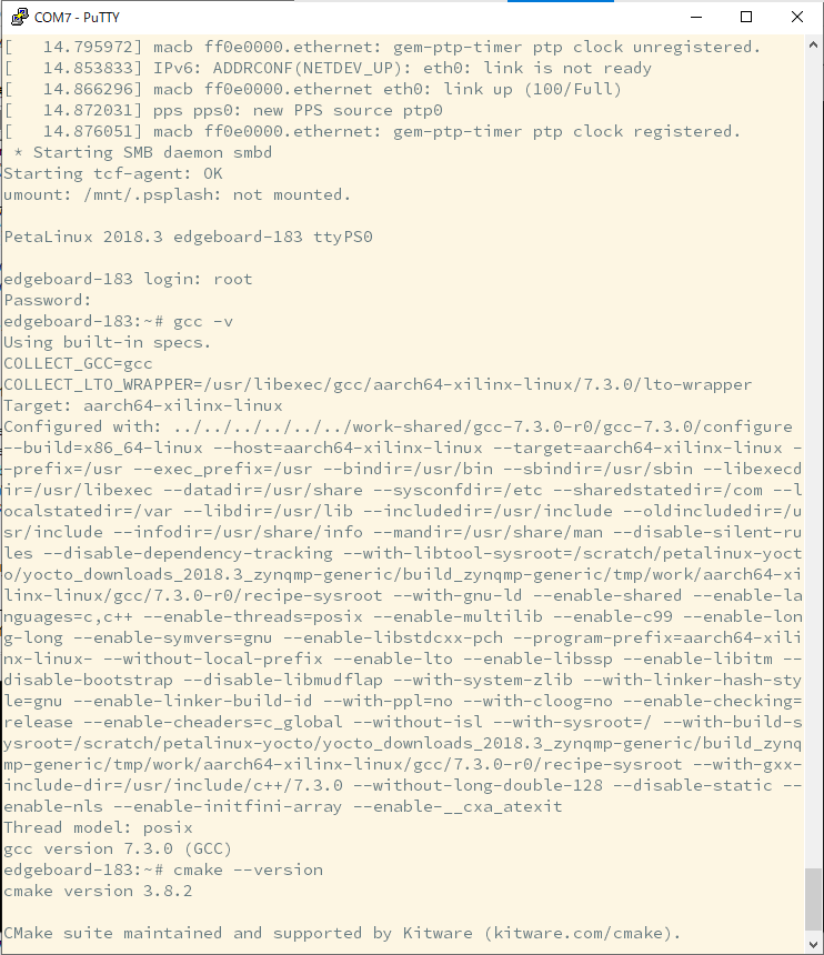
Note for PuTTY users: disabling flow control is necessary for proper console input.
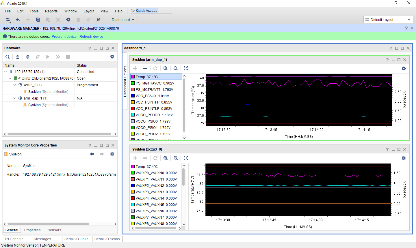
After starting hwserver as described in the previous article and connecting Vivado to the hwserver instance, we can see that the two TAPs are correctly recognized, and data from various on-chip sensors can be read from the two SysMon devices.
Further functional tests about the shipped AI core can also be performed following the hardware manual from Baidu and ALINX (designer and manufacturer of PCB), and will not be covered here.
Gallery
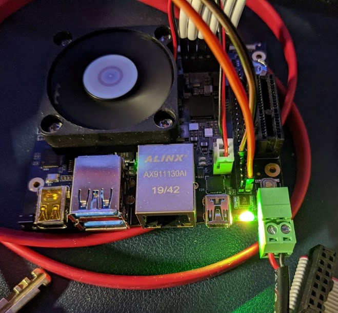
Main visual of the Edgeboard in working state:
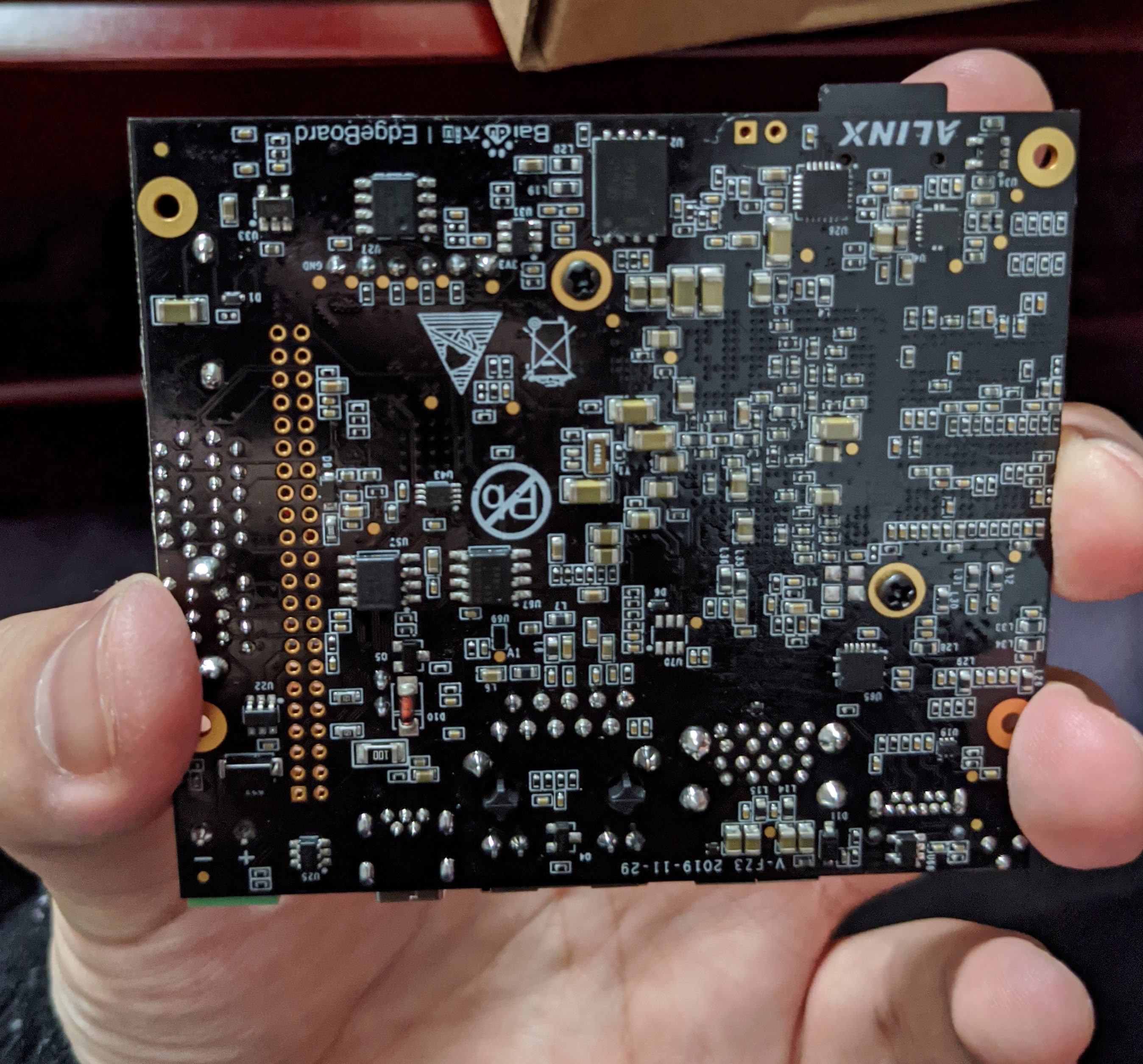
Unsoldered GPIO pads:
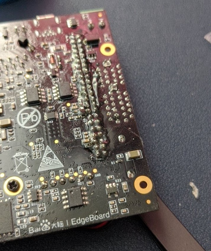
After soldering:
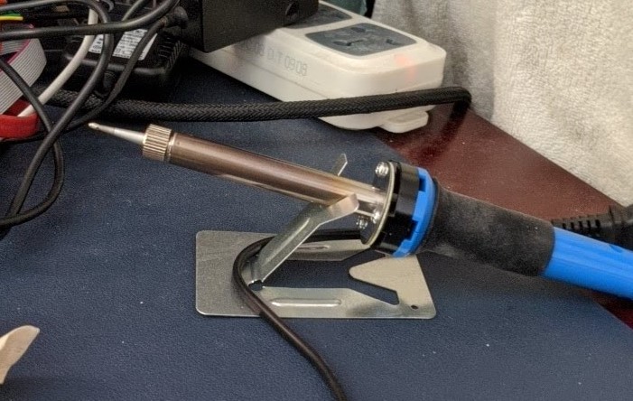
Solder iron used:
JTAG cable used: